Solutions for Interference Problems Of Led Drivers
Posted By Ottima Technology Co.ltd on 2020-06-29 8:39 AM

Description
The interference problem of CE LED driver is not easy to solve. The main reason is that the impact of interference is often unpredictable and unpredictable. How can this problem be done well in the face of various interferences of different sizes, You need to find the source of the interference problem.
1. Reasons for interference caused by LED driver
Constant voltage led driver first rectifies the power frequency AC to DC, and then inverts to high frequency, and then outputs it through the rectifier filter circuit to obtain a stable DC voltage, so it contains a lot of harmonic interference. At the same time, due to the leakage inductance of the transformer and the spike caused by the reverse recovery current of the output diode, electromagnetic interference is formed. The interference sources in the switching power supply are mainly concentrated on the components with large changes in voltage and current, which are prominently displayed on the switch tube, diode, and high-frequency transformer.

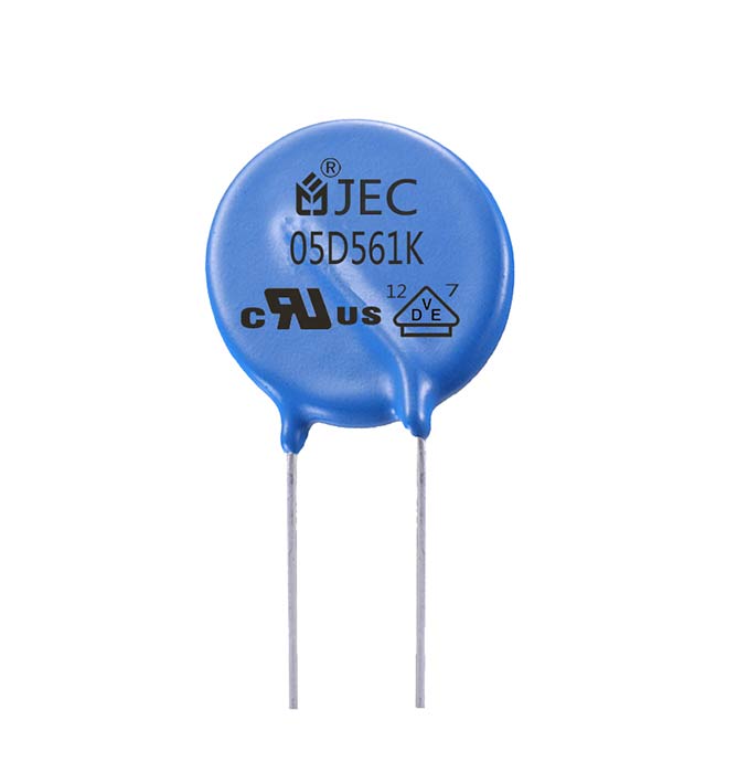
Constant Voltage Led Driver
① Electromagnetic interference generated by the switching circuit
The switching circuit is one of the main interference sources of the switching power supply. The switching circuit is the core of the switching power supply (the same is true for the LED street lamp power supply and the LED tunnel lamp driving power supply), which is mainly composed of a switch tube and a high-frequency transformer. The du / dt it produces has a larger amplitude pulse, a wider frequency band and rich harmonics. The main reason for this pulse interference is: the switch tube load is the primary coil of the high-frequency transformer, which is an inductive load. At the instant when the switch is turned on, the primary coil generates a large inrush current, and a high surge peak voltage appears at both ends of the primary coil; when the switch is turned off, due to the leakage flux of the primary coil, part of the energy is not From the primary coil to the secondary coil, this part of the energy stored in the inductor will form a peaked attenuation oscillation with the capacitor and resistance in the collector circuit, superimposed on the turn-off voltage, forming a turn-off voltage spike. The interruption of the power supply voltage will produce the same magnetizing inrush current transient as when the primary coil is turned on. This transient is a conductive electromagnetic interference, which not only affects the transformer primary, but also returns the conducted interference to the distribution system, causing grid harmonics. Electromagnetic interference, which affects the safety and economic operation of other equipment.
② Electromagnetic interference generated by the rectifier circuit
In the rectifier circuit, there is a reverse current when the output rectifier diode is cut off. The time for it to return to zero is related to factors such as junction capacitance. Among them, the diode that can quickly recover the reverse current to zero is called a hard recovery characteristic diode. This diode will produce strong high-frequency interference under the influence of transformer leakage inductance and other distributed parameters, and its frequency can reach tens of MHz . A large forward current flows when the rectifier diode in the high-frequency rectifier circuit is turned on in the forward direction. When it is turned off by the reverse bias voltage, there are more carriers accumulated in the PN junction. A period of time before the vanishes, the current will flow in the reverse direction, causing the reverse recovery current for the vanishing of the carriers to decrease sharply and a large current change will occur.
③ High frequency transformer
The high-frequency switching current loop composed of the primary coil, switch tube and filter capacitor of the high-frequency transformer may generate large spatial radiation, which forms radiation interference. If the filtering capacity of the capacitor is insufficient or the high-frequency characteristics are not good, the high-frequency impedance on the capacitor will cause the high-frequency current to be conducted into the AC power in a differential mode to form conducted interference. It should be noted that in the electromagnetic interference generated by the diode rectifier circuit, the di / dt of the reverse recovery current of the rectifier diode is much larger than that of the reverse recovery current of the freewheeling diode. Researched as a source of electromagnetic interference, the reverse recovery current formed by the rectifier diode has large interference intensity and frequency bandwidth. However, the voltage jump generated by the rectifier diode is much smaller than the voltage jump generated when the power switch is turned on and off. Therefore, the influence of the rectifier diode can be ignored, and the rectifier circuit can be considered as part of the electromagnetic interference coupling channel.
④Interference caused by distributed capacitance
The switching power supply works in a high-frequency state, so its distributed capacitance cannot be ignored. On the one hand, the contact area of the insulating sheet between the heat sink and the collector of the switch tube is large, and the insulating sheet is thin, so the distributed capacitance between the two cannot be ignored at high frequencies. High-frequency current will flow to the heat sink through the distributed capacitor and then to the chassis ground, causing common mode interference; on the other hand, there is a distributed capacitor between the primary and secondary of the pulse transformer, which can directly couple the primary voltage to the secondary In the above, the common-mode interference is generated on the two power lines for DC output on the secondary side.
⑤ Stray parameters affect the characteristics of the coupling channel
In the conducted interference frequency band (<30MHz), most of the coupling channels of switching power supply interference can be described by circuit networks. However, any actual component in the switching power supply, such as resistance, capacitance, inductance and even the switch tube and diode, contains stray parameters, and the wider the frequency band studied, the higher the order of the equivalent circuit. Therefore, the equivalent circuit of the switching power supply including the stray parameters of each component and the coupling between the components will be much more complicated. At high frequencies, stray parameters have a great influence on the characteristics of the coupling channel, and the presence of distributed capacitance becomes a channel for electromagnetic interference. In addition, when the power of the switch tube is large, the collector generally needs to add a heat sink. The distributed capacitance between the heat sink and the switch tube cannot be ignored at high frequencies. It can form space-oriented radiation interference and power line conduction. Common mode interference.
Second, the control technology of electromagnetic interference of switching power supply
To solve the electromagnetic interference problem of the 30w LED driver, you can start from three aspects: 1) reduce the interference signal generated by the interference source; 2) cut off the propagation path of the interference signal; 3) enhance the resistance of the interfered body Interference ability. Therefore, the main control technologies for electromagnetic interference of switching power supply are: circuit measures, EMI filtering, component selection, shielding and anti-interference design of printed circuit boards.
① Reduce the interference of the switching power supply itself
Soft switching technology: add inductance and capacitance elements to the original hard switching circuit, use the resonance of inductance and capacitance to reduce du / dt and di / dt during the switching process, so that the voltage drop when the switching device is turned on precedes the current rise , Or when the current is turned off, the fall of the current precedes the rise of the voltage to eliminate the overlap between the voltage and the current.
Switching frequency modulation technology: By modulating the switching frequency fc, the energy concentrated on fc and its harmonics 2fc, 3fc ... is distributed to the frequency bands around them to reduce the EMI amplitude at each frequency point. This method cannot reduce the total amount of interference, but the energy is dispersed to the baseband of the frequency points, so that each frequency point does not exceed the limit specified by EMI. In order to achieve the purpose of reducing the peak of the noise spectrum, there are usually two processing methods: random frequency method and modulation frequency method.
Selection of components: Select components that are not easy to generate noise, easy to conduct and radiate noise. Of particular note is the selection of winding components such as diodes and transformers. Fast recovery diodes with small reverse recovery current and short recovery time are ideal devices for high-frequency rectification of switching power supplies.
Active suppression technology for common mode interference: try to take a compensated EMI noise voltage completely out of phase with the main switching voltage waveform causing electromagnetic interference from the main loop, and use it to balance the original switching voltage.

30w Led Driver
Filtering: One of the main purposes of the EMI filter is to obtain higher insertion loss in the frequency range of 150kHz to 30MHz, but it does not attenuate the 50Hz power frequency signal, so that the rated voltage and current can pass smoothly. Meet certain size requirements. The conducted interference signals on any power line can be represented by differential mode and common mode signals. In general, the differential mode interference amplitude is small, the frequency is low, and the interference caused is small; the common mode interference amplitude is large, the frequency is high, and radiation can also be generated through the wire, which causes large interference. Therefore, to weaken the conducted interference and control the EMI signal below the limit level specified by the relevant EMC standards, an effective method is to install an electromagnetic interference filter in the input and output circuits of the switching power supply.
PCB design: PCB anti-interference design mainly includes PCB layout, wiring and grounding, and its purpose is to reduce the electromagnetic radiation of PCB and crosstalk between the circuits on the PCB. The method of switching power supply layout is similar to its electrical design. After determining the size and shape of the PCB, determine the location of special components (such as various generators, crystal oscillators, etc.). Then, according to the functional unit of the circuit, all the components of the circuit are laid out.
Buffer circuit to reduce electromagnetic interference: It consists of a linear impedance stable network. Its function is to eliminate potential interference in the power supply line, including power line interference, rapid electrical transients, surges, voltage level changes, and power line harmonics. These interferences are not great for general regulated power supplies, but they have a significant impact on high-frequency switching power supplies.
② Cut off the propagation of interference signals-common mode and differential mode power line filter design
Power line interference can be filtered using a power line filter. A reasonable and effective switching power supply EMI filter should have a strong suppression effect on the differential mode and common mode interference on the power line.
③Enhance the anti-interference ability of sensitive circuits
We are an ultra-thin LED driver supplier, if you are interested in our products, please feel free to contact us.
Tags: china oem led,driver, led power, led,adaptor supplier
For more information, please Click HereRatings & Review
Last Viewed Blogs
Solutions for Interference Problems Of Led Drivers
Solutions for Interference Problems Of Led Drivers
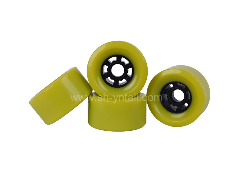
Advantages of Pu wheels
Advantages of Pu wheels
What Are The Probable Household Moving Faults Which Lead To Disastrous End Result Presented By Packers And Movers In Bangalore
What Are The Probable Household Moving Faults Which Lead To Disastrous End Result Presented By Packers And Movers In Bangalore